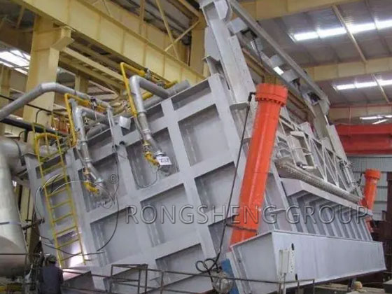
The tilting refining furnace is one of the common thermal equipment in non-ferrous metal smelting. Its outer shell is a steel shell structure, and its inner lining is composed of refractory brick furnace lining. The tilting furnace can be divided into three parts according to the structure of the furnace body, namely the furnace bottom, furnace wall and furnace top. Before construction, use a theodolite to measure the centerline of the furnace. Re-measure the design elevations of the furnace door, reverse arch, furnace wall and furnace roof arch feet of the tilting furnace in the normal position, and mark them on the inside of the furnace shell steel plate as the baseline for building the furnace bottom and furnace walls.
The Masonry of the Furnace Bottom
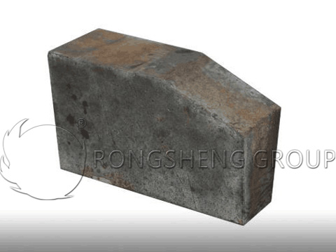
The bottom of the furnace is in the shape of a reverse arch with a total thickness of about 600-700mm. It is generally built with three materials and three grades of refractory materials. As shown in Figure 1. The pre-poured anti-arch arc-shaped furnace bottom should be based on the designed arc of the metal furnace shell, and the center line should be found along the length direction. Draw the arc shape of the reverse arch and the height of the vault on the furnace shell. Accordingly, a concave formwork is set up and refractory castable is poured. The castable has two layers and one layer according to the design. For furnace bottoms with two layers of castables, the lightweight castable next to the steel plate layer should be poured first. When pouring, it should be carried out in cross sections, tamped by hand, and smoothed according to the upper surface of the template. The first batch of castables can be removed from the mold after curing for one day, and then the second batch is poured. The joints between old and new castables do not require special treatment.
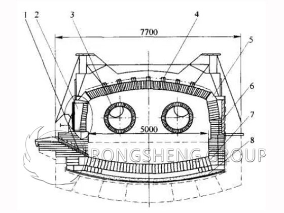
1—Copper outlet. 2—Feeding port. 3—Burner mouth. 4—Suspended bricks from the roof. 5—Head arch bricks. 6—Magnesia chrome bricks. 7—Reverse arch foot bricks. 8—Refractory castables.
The arc-shaped furnace bottom with a reverse arch should find the center line along the length direction according to the arc required by the design. Draw the arc of the reverse arch on the furnace shell, set up a concave template accordingly, and pour the refractory pouring section. The pouring should be carried out in cross sections, tamped by hand, and smoothed according to the upper surface of the formwork. The surface must be treated according to design requirements before initial setting.
During the pouring process, due to the high viscosity of the refractory castable mixture and poor fluidity, attention must be paid to the tamping work. The insertion point of a plug-in vibrator should be dense, and removal of the vibrator should be done slowly and steadily. The joints between old and new castables do not require special treatment. The curing time should be carried out according to the requirements provided by the refractory material supplier.
After the pouring layer has been cured and dried, use a theodolite to measure the longitudinal centerline and check whether the arc of the reverse arch meets the requirements. When confirmed, start pouring the magnesia-chromium castable. The pouring requirements and methods are the same as the first layer. Magnesia-chrome brick masonry is carried out symmetrically from the longitudinal center line to both sides.
The reverse arch bricks start from the center line of one end of the furnace and are laid to both sides at the same time. During construction, a ring is laid first, and then the ring is used as a standard to build the bricks one by one. The brick ring of the first ring of bricks must be flat and vertical and close to the furnace end wall. Both longitudinal and transverse expansion joints should be dispersed and left as designed. The bricks on both sides of the arch connecting the furnace wall must be built into the wall. After the arch is completed, it should be covered with linoleum. When the reverse arch is wet-layed, the thickness of the brick joint should be 2mm less than the thickness of the annular joint between the two layers of reverse arch. When laying wet, brick joints should be dried. Far infrared drying equipment can be used.
The Masonry of the Furnace Wall
The furnace wall should start from the furnace mouth and pouring mouth, as well as the redox intubation and the four corners at the same time, and draw the wires layer by layer. It is necessary to ensure the bottom elevation of the furnace mouth and pouring port, the center elevation of the redox intubation and the installation angle, and ensure that the wall is horizontally and vertically. For the two burner holes on the end wall, the center elevation of the hole should be determined first, and then the horizontal bottom elevation should be found. Determine the installation angle and internal opening angle according to the center elevation and horizontal bottom elevation. The burner hole brick can be supplied together with the burner, or it can be poured on site. The cast-in-place burner hole bricks must reach their strength before use.
There is a smoke outlet on the wall at the other end, and the center line of the smoke outlet is at the tilting center of the furnace. Before masonry, find the center elevation of the hole and determine the horizontal bottom elevation. First build the lower part according to the section of the smoke exhaust outlet. After the lower part is built, use wooden pillars to support the arch and start building half of the arch. After the arch is built, continue building the wall.
The Masonry of the Roof bricks
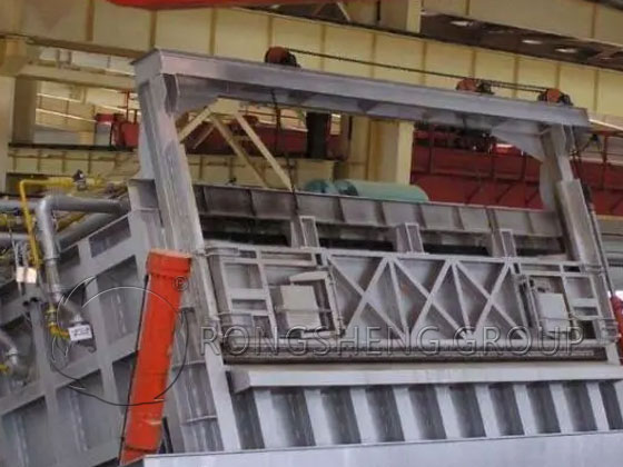
The furnace roof brick is a hanging structure, the furnace roof span is large, and the arch tire support must be firm. Before supporting the arch tire, use a level to measure the horizontal elevation of the arch foot, and draw the design elevation line for the arch tire accordingly. The actual elevation of the arch tire should be slightly lower than the measured horizontal elevation of the arch foot. The spacing between arch frames is 450~500mm, and the load-bearing beams must be supported on the nodes of the arch frames. The longitudinal distance between the pillars shall not be greater than 800mm. The vertical and horizontal diagonal braces between the supports must be nailed firmly, and the lower parts of the pillars shall be wedged tightly with wooden wedges. A 30mm wide gap can be left between the arch tire and the furnace wall. After the tire arch is supported, supports should be added at both ends to fix it.
Before laying the furnace roof, check whether the rod height of the arch foot beam (table) meets the requirements and whether the welding is smooth.
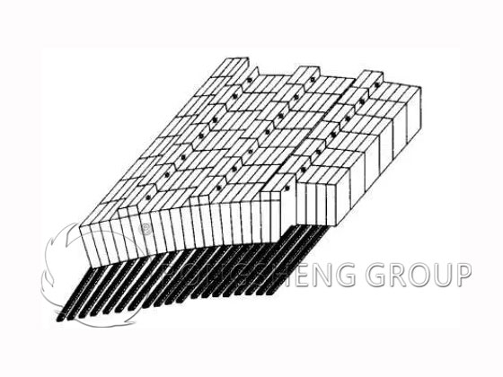
When building suspended vaults, they are generally built symmetrically from the arch feet on both sides to the center, as shown in Figure 2. First try to build a ring, the arch foot brick and the first arch brick are wet laid, and the brick ring is straightened strictly according to the regulations. Next, insert the pins into the holes of the bricks and build the second arch brick. At the same time, set two corresponding positioning arch foot bricks, and make their angle and position meet the design requirements. Then draw through lines along the upper and lower edges of the surface of the arch bricks, and build the arch bricks on both sides accordingly. The foot bricks of the suspended vault must be raised to the foot beams. The expansion joints of the brick masonry at the arch foot should be centrally located, and their location is generally at the arch foot. Based on the joints of the beams, other brick rings are laid in sequence. Aluminized pins and 0.5mm thick steel spacers are inserted between the bricks, and 1mm thick cardboard is sandwiched between every two bricks. The hanging vault should be divided into rings and locked, and the locking degree of each ring should be consistent. After the locking bricks are closed tightly, the long hanging pins should be threaded immediately.
After the furnace roof masonry is completed, the arch tires can only be removed after the hanging steel parts are installed and the tie rods between the columns are tightened.
The quality of masonry must ensure that the inner surface is smooth, and the height of the staggered teeth of individual bricks does not exceed 2mm. The bricks in each ring are arranged evenly and neatly, and the door bricks are evenly distributed.
The masonry of the burner hole and furnace roof in the furnace door area. The furnace door is located between two columns, and its lock brick should be placed in the middle of the arch, with wedge bricks built from both sides to the middle, as shown in Figure 3.
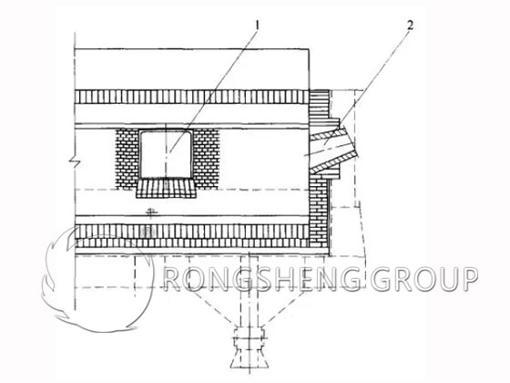
1-Feeding door. 2-Burner hole.
One side of the lock brick must be embedded in the bricklayer, and no straight seam shall be left. The masonry expansion joints in the furnace door area can be consistent with the expansion joints of the arch foot bricks.